By Kevin Custer

Concept & Use:
The use of this Isolated Tap Plate will allow you to separate signals
to allow testing of plant without needing to remove cables from a tap location.
This device can be placed into the line, at a convenient place, to allow
response tests and the attachment of a TDR to the plant.
Description:
This IT plate can be configured to temporarily replace any tap plate.
This is done by connecting common drop passives to the appropriate F connections.
The plate will also allow the use of a non directional coupler to be placed
into the system to see response problems in the feeder. The plate
shown here was designed to be used in a Magnavox system, however any style
plate can be configured similarly to allow testing.
The IT plate blocks the AC voltage from passing from the input to the output if present. AC voltage is also blocked to the F connections to allow common drop passives and a non directional coupler (NDC) to be used without the risk of damage. A TDR can also be connected directly to the F ports to allow easy shooting of each independent line to or from the tap.
Advantages:
The use of this device will allow you to keep as much of the plant
on as possible by only interrupting the line past this plate. Quick
testing of the affected line will allow the determination of the damage.
Since the plate will allow a TDR to be connected, several different
tests can be performed by the use of this one plate.
Construction:
I construct the IT plate from a common 2 port tap plate . The
use of any value except a 4-2 will work since both seizure connection
mechanisms are needed. Simply remove the plate from the casting,
and then remove the circuit board and gut the tap plate by removing all
components. Salvage the two RF coupling capacitors as they will be
used to connect the seizure mechanisms to the F ports.
Connect a 750 pF, or similar value mylar capacitor, salvaged from the
gutting of the plate, from the seizure connection mechanism to the appropriate
F connector using the shortest possible path. This is done in both
locations.
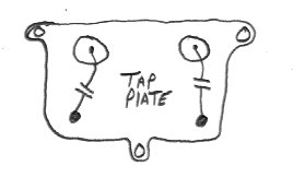
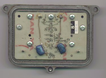
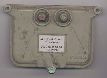
Refer to these images to understand construction.
Tap plate layout.
Tap plate bottom.
Tap plate top.
The information presented here is Copyrighted 1999 by Kevin Custer